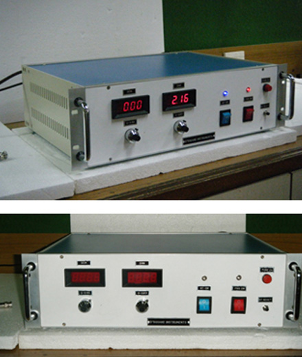
0 – 10 kv DC POWR SUPPLY
SPECIFICATIONS
| Input : |
230V AC±10%, 50Hz single phase. |
| Output |
0 to ± 10KV continuously variable. |
| Current Capacity |
5mA max. |
| Load regulation |
0.1% for change in load from N.L. to F.L. |
| Line regulation |
0.1% for change in line voltage from 207V to 253V. |
| Ripple |
Less than 100 mV r.m.s. |
| Metering |
Two separate digital front panel meters should be provided to monitor output voltage and load current continuously |
| Meter accuracy |
±2% of full scale |
| Protection |
The power supply is protected against over load and short circuit conditions. |
| Set current limit |
Ten turn potentiometer on front panel to set current from 0-10mA. |
| Set Output Voltage |
Ten turn potentiometer on front panel to set HV from 0-10KVdc. |
| Dimensions |
(L-240xW-120xD-260)mm approximately |
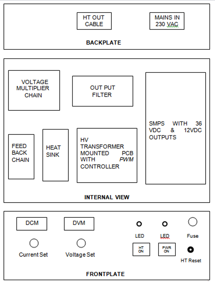
BLOCK DIAGRAM
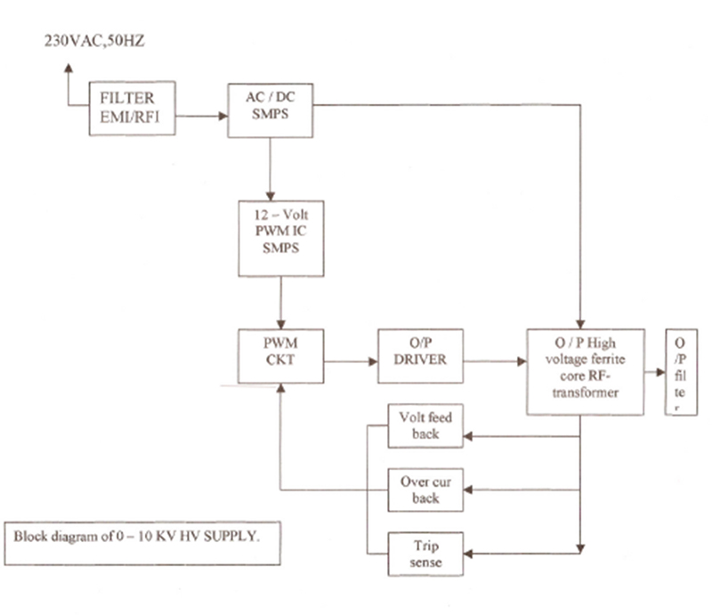
CIRCUIT DESCRIPTION
- The input ckt. consists of fuse protected Switched Mode Power Supply (SMPS).
- This power supply is having efficiency around 85%. It generates low voltage viz. 12 V DC and 36 VDC.
- The 12 VDC supply is used for biasing PWM converter and to
- generate reference voltage for error amplifier. It is also used for indicating circuits. A tripping circuit, which limits the output current, is also fed through this voltage.
- The 36 VDC supply has the capacity to give high driving current.
- This SMPS has built-in over current, over voltage & ULVO protections as well the Auto Fold-back Recovery type function.
- The out power circuits are biased with this supply.
- A third supply is 15 V transformer generated AC voltage source that feeds the voltage to floating DPMs.
- A high voltage transformer is used to generate high voltage.
- It is a potted ferrite-core transformer, which generates 2 KV AC square wave voltage.
- This voltage is further multiplied to 10 KV DC high voltage by a Voltage Multiplier Chain. The chain has a combination of high voltage fast acting diodes and loss less high voltage capacitors.
- The output DC voltage is filtered and given out through high voltage BNC cable.
- A feedback chain monitors the output voltage. The differential signal due to load with respect to reference voltage as per the SET VALUE is fed to the error amplifier, which in turns corrects the out put voltage to the SET VALUE.
- A separate voltage resistor chain is used to monitor output voltage with digital meter.
- Current at output is sampled and if it exceeds the SET CURRENT limit the circuit will trip.
- The PWM circuit is used to regulate the output voltage by basically altering the pulse width to maintain the level of regulation.
OUTPUT VOLTAGE = PRIMARY VOLTAGE * TURNS
RATIO * DUTY FACTOR
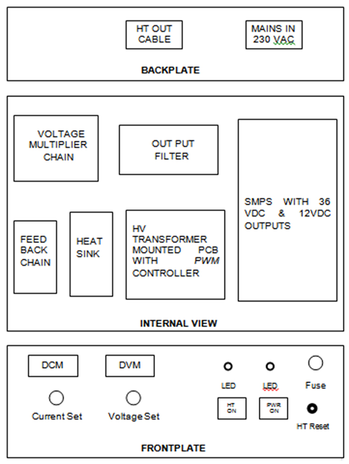
FUNCTION OF CONTROLS / INDICATORS
- 0 – 10 KV VOLT – SET : It’s a 10-turn pot meter to adjust output voltage
- 0 – 10 mA CURR – SET : It’s a 10-turn pot meter to adjust trip value of output current.
- DVM : Indicates output voltage.
- DCM : Indicates output current.
- PWR ON : To switch ON the power.
- HT ON : To switch ON the HT.
- RED LED : Indicates power ON.
- BLUE LED : Indicates HT ON.
- HT RESET : To reset the supply after HT TRIP
FIRST TIME OPERATION
- Put PWR switch in OFF position.
- Put HT ON switch in OFF position.
- Rotate 0 – 10 KV 10-turns pot meter to zero.
- Rotate 0 – 5 mA 10-turns pot meter to zero.
- Check 230 VAC at Input Mains.
- Switch ON the PWR ON switch.
- Switch ON the HT ON switch.
- Slowly rotate 0-10 kv pot meter clockwise. The voltage starts increasing from 2.2-mark on window onwards. Set the voltage to required value as indicated on DVM.
- Set the Current tripping value as required & can be seen on DCM.
- When load current increases more than the set tripping value, the supply will trip. DO NOT RESET THE SWITCH immediately. Rotate the 0-10 kv pot meter anti clock wise to zero. Then RESET the switch. Now, supply can be started as usual.
- Always operate the supply in clean and air-conditioned environment.
GENERAL LAYOUT
WARRANTY
D’SQUARE INSTRUMENTS offers standard warranty of 12 months onto the power supply, which is applicable from the date of sale.
The company will undertake repairs or replacement of any part, required if any only due to manufacturing defect and not due to mishandling or improper installation or against input supply defects & natural calamities like fire, flood & earthquake etc.
0 – 15 kv DC POWR SUPPLY
SPECIFICATIONS
| Input : |
230V AC±10%, 50Hz single phase. |
| Output |
0 to ± 15KV continuously variable. |
| Current Capacity |
3mA max. |
| Load regulation |
0.1% for change in load from N.L. to F.L. |
| Line regulation |
0.1% for change in line voltage from 207V to 253V. |
| Ripple |
Less than 100 mV r.m.s. |
| Metering |
Two separate digital front panel meters should be provided to monitor output voltage and load current continuously |
| Meter accuracy |
±2% of full scale |
| Protection |
The power supply is protected against over load and short circuit conditions. |
| Set current limit |
Ten turn potentiometer on front panel to set current from 0-5mA. |
| Set Output Voltage |
Ten turn potentiometer on front panel to set HV from 0-15KVdc. |
| Dimensions |
(L-240xW-120xD-260)mm approximately |
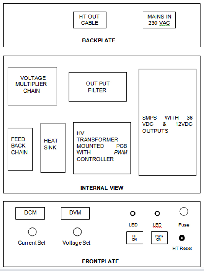
BLOCK DIAGRAM
CIRCUIT DESCRIPTION
- The input ckt. consists of fuse protected Switched Mode Power Supply (SMPS).
- This power supply is having efficiency around 85%. It generates low voltage viz. 12 V DC and 36 VDC.
- The 12 VDC supply is used for biasing PWM converter and to
- generate reference voltage for error amplifier. It is also used for indicating circuits. A tripping circuit, which limits the output current, is also fed through this voltage.
- The 36 VDC supply has the capacity to give high driving current.
- This SMPS has built-in over current, over voltage & ULVO protections as well the Auto Fold-back Recovery type function.
- The out power circuits are biased with this supply.
- A third supply is 15 V transformer generated AC voltage source that feeds the voltage to floating DPMs.
- A high voltage transformer is used to generate high voltage.
- It is a potted ferrite-core transformer, which generates 2 KV AC square wave voltage.
- This voltage is further multiplied to 15 KV DC high voltage by a Voltage Multiplier Chain. The chain has a combination of high voltage fast acting diodes and loss less high voltage capacitors.
- The output DC voltage is filtered and given out through high voltage BNC cable.
- A feedback chain monitors the output voltage. The differential signal due to load with respect to reference voltage as per the SET VALUE is fed to the error amplifier, which in turns corrects the out put voltage to the SET VALUE.
- A separate voltage resistor chain is used to monitor output voltage with digital meter.
- Current at output is sampled and if it exceeds the SET CURRENT limit the circuit will trip.
- The PWM circuit is used to regulate the output voltage by basically altering the pulse width to maintain the level of regulation.
OUTPUT VOLTAGE = PRIMARY VOLTAGE * TURNS RATIO * DUTY FACTOR
FUNCTION OF CONTROLS / INDICATORS
- 0 – 15 KV VOLT – SET : It’s a 10-turn pot meter to adjust output voltage
- 0 – 1 mA CURR – SET: It’s a 10-turn pot meter to adjust trip value of output current.
- DVM : Indicates output voltage.
- DCM : Indicates output current.
- PWR ON : To switch ON the power.
- HT ON : To switch ON the HT.
- RED LED : Indicates power ON.
- BLUE LED : Indicates HT ON.
- HT RESET : To reset the supply after HT TRIP
FIRST TIME OPERATION
- Put PWR switch in OFF position.
- Put HT ON switch in OFF position.
- Rotate 0 – 15 KV 10-turns pot meter to zero.
- Rotate 0 – 5 mA 10-turns pot meter to zero.
- Check 230 VAC at Input Mains.
- Switch ON the PWR ON switch.
- Switch ON the HT ON switch.
- Slowly rotate 0-15 kv pot meter clockwise. The voltage starts increasing from 2.2-mark on window onwards. Set the voltage to required value as indicated on DVM.
- Set the Current tripping value as required & can be seen on DCM.
- When load current increases more than the set tripping value, the supply will trip. DO NOT RESET THE SWITCH immediately. Rotate the 0-15 kv pot meter anti clock wise to zero. Then RESET the switch. Now, supply can be started as usual.
- Always operate the supply in clean and air-conditioned environment.
GENERAL LAYOUT
WARRANTY
D’SQUARE INSTRUMENTS offers standard warranty of 12 months onto the power supply, which is applicable from the date of sale.
The company will undertake repairs or replacement of any part, required if any only due to manufacturing defect and not due to mishandling or improper installation or against input supply defects & natural calamities like fire, flood & earthquake etc.
0 – 25 kv DC POWR SUPPLY
SPECIFICATIONS
| Input : |
48V DC±10%, Battery Voltage. |
| Output |
0 to + 25KV continuously variable. |
| Current Capacity |
1mA max. |
| Load regulation |
0.5% for change in load from N.L. to F.L. |
| Line regulation |
0.5% for change in i/p voltage within range +/- 10%. |
| Ripple |
Less than 100 mV r.m.s. |
| Metering |
Two separate digital front panel meters should be provided to monitor output voltage and load current continuously |
| Meter accuracy |
±2% of full scale |
| Protection |
The power supply is protected against over load and short circuit conditions. |
| Set current limit |
Ten turn potentiometer on front panel to set current from 0-1mA. |
| Set Output Voltage |
Ten turn potentiometer on front panel to set HV from 0-25KVdc. |
| Dimensions |
(L-240xW-120xD-260)mm approximately |
BLOCK DIAGRAM
CIRCUIT DESCRIPTION
- The input ckt. consists of fuse protected Switched Mode Power Supply (SMPS).
- This power supply is having efficiency around 85%. It generates low voltage viz. 12 V DC and 36 VDC.
- The 12 VDC supply is used for biasing PWM converter and to
- generate reference voltage for error amplifier. It is also used for indicating circuits. A tripping circuit, which limits the output current, is also fed through this voltage.
- The 36 VDC supply has the capacity to give high driving current.
- This SMPS has built-in over current, over voltage & ULVO protections as well the Auto Fold-back Recovery type function.
- The out power circuits are biased with this supply.
- A third supply is 15 V transformer generated AC voltage source that feeds the voltage to floating DPMs.
- A high voltage transformer is used to generate high voltage.
- It is a potted ferrite-core transformer, which generates 2 KV AC square wave voltage.
- This voltage is further multiplied to 25 KV DC high voltage by a Voltage Multiplier Chain. The chain has a combination of high voltage fast acting diodes and loss less high voltage capacitors.
- The output DC voltage is filtered and given out through high voltage BNC cable.
- A feedback chain monitors the output voltage. The differential signal due to load with respect to reference voltage as per the SET VALUE is fed to the error amplifier, which in turns corrects the out put voltage to the SET VALUE.
- A separate voltage resistor chain is used to monitor output voltage with digital meter.
- Current at output is sampled and if it exceeds the SET CURRENT limit the circuit will trip.
- The PWM circuit is used to regulate the output voltage by basically altering the pulse width to maintain the level of regulation.
OUTPUT VOLTAGE = PRIMARY VOLTAGE * TURNS RATIO * DUTY FACTOR
FUNCTION OF CONTROLS / INDICATORS
- 0 – 25 KV VOLT – SET : It’s a 10-turn pot meter to adjust output voltage
- 0 – 1 mA CURR – SET: It’s a 10-turn pot meter to adjust trip value of output current.
- DVM : Indicates output voltage.
- DCM : Indicates output current.
- PWR ON : To switch ON the power.
- HT ON : To switch ON the HT.
- RED LED : Indicates power ON.
- BLUE LED : Indicates HT ON.
- HT RESET : To reset the supply after HT TRIP
FIRST TIME OPERATION
- Put PWR switch in OFF position.
- Put HT ON switch in OFF position.
- Rotate 0 – 25 KV 10-turns pot meter to zero.
- Rotate 0 – 1 mA 10-turns pot meter to zero.
- Check 48 VDC at Input.
- Switch ON the PWR ON switch.
- Switch ON the HT ON switch.
- Slowly rotate 0-25 kv pot meter clockwise. The voltage starts increasing from 2.2-mark on window onwards. Set the voltage to required value as indicated on DVM.
- Set the Current tripping value as required & can be seen on DCM.
- When load current increases more than the set tripping value, the supply will trip. DO NOT RESET THE SWITCH immediately. Rotate the 0-25 kv pot meter anti clock wise to zero. Then RESET the switch. Now, supply can be started as usual.
- Always operate the supply in clean and air-conditioned environment.
GENERAL LAYOUT
WARRANTY
D’SQUARE INSTRUMENTS offers standard warranty of 12 months onto the power supply, which is applicable from the date of sale.
The company will undertake repairs or replacement of any part, required if any only due to manufacturing defect and not due to mishandling or improper installation or against input supply defects & natural calamities like fire, flood & earthquake etc.
0 – 30 kv DC POWR SUPPLY
SPECIFICATIONS
| Input : |
230V AC±10%, 50Hz single phase. |
| Output |
0 to ± 30KV continuously variable. |
| Current Capacity |
2mA max. |
| Load regulation |
0.5% for change in load from N.L. to F.L. |
| Line regulation |
: 0.5% for change in line voltage from 207V to 253V. |
| Ripple |
Less than 1 mV r.m.s. |
| Metering |
Two separate digital front panel meters provided to monitor output voltage and load current continuously |
| Meter accuracy |
±2% of full scale |
| Protection |
The power supply is protected against over load and short circuit conditions. |
| Set current limit |
Ten turn potentiometer on front panel to set current from 0-2mA. |
| Set Output Voltage |
Ten turn potentiometer on front panel to set HV from 0-30KVdc. |
| Dimensions |
Rack 19” Height 3 U (approximately) |
BLOCK DIAGRAM
CIRCUIT DESCRIPTION
- The input ckt. consists of fuse protected Switched Mode Power Supply (SMPS).
- This power supply is having efficiency around 85%. It generates low voltage viz. 12 V DC and 36 VDC.
- The 12 VDC supply is used for biasing PWM converter and to
- generate reference voltage for error amplifier. It is also used for indicating circuits. A tripping circuit, which limits the output current, is also fed through this voltage.
- The 36 VDC supply has the capacity to give high driving current.
- This SMPS has built-in over current, over voltage & ULVO protections as well the Auto Fold-back Recovery type function.
- The out power circuits are biased with this supply.
- A third supply is 15 V transformer generated AC voltage source that feeds the voltage to floating DPMs.
- A high voltage transformer is used to generate high voltage.
- It is a potted ferrite-core transformer, which generates 1.5 KV AC square wave voltage.
- This voltage is further multiplied to 30 KV DC high voltage by a Voltage Multiplier Chain. The chain has a combination of high voltage fast acting diodes and loss less high voltage capacitors.
- The output DC voltage is filtered and given out through high voltage cable connector.
- A feedback chain monitors the output voltage. The differential signal due to load with respect to reference voltage as per the SET VALUE is fed to the error amplifier, which in turns corrects the out put voltage to the SET VALUE.
- A separate voltage resistor chain is used to monitor output voltage with digital meter.
- Current at output is sampled and if it exceeds the SET CURRENT limit the circuit will trip.
- The PWM circuit is used to regulate the output voltage by basically altering the pulse width to maintain the level of regulation.
OUTPUT VOLTAGE = PRIMARY VOLTAGE * TURNS RATIO * DUTY FACTOR
FUNCTION OF CONTROLS / INDICATORS
- 0 – 30 KV VOLT – SET : It’s a 10-turn pot meter to adjust output voltage
- 0 – 1 mA CURR – SET: It’s a 10-turn pot meter to adjust trip value of output current.
- DVM : Indicates output voltage.
- DCM : Indicates output current.
- PWR ON : To switch ON the power.
- HT ON : To switch ON the HT.
- RED LED : Indicates power ON.
- BLUE LED : Indicates HT ON.
- HT RESET : To reset the supply after HT TRIP
FIRST TIME OPERATION
- Put PWR switch in OFF position.
- Put HT ON switch in OFF position.
- Rotate 0 – 30 KV 10-turns pot meter to zero.
- Rotate 0 – 1 mA 10-turns pot meter to zero.
- Check 230 VAC at Input Mains.
- Switch ON the PWR ON switch.
- Switch ON the HT ON switch.
- Slowly rotate 0-30 kv pot meter clockwise. Set the voltage to required value as indicated on DVM.
- Set the Current tripping value as required & can be seen on DCM.
- When load current increases more than the set tripping value, the supply will trip. DO NOT RESET THE SWITCH immediately. Rotate the 0-30 kv pot meter anti clock wise to zero. Then RESET the switch. Now, supply can be started as usual.
- Always operate the supply in clean and air-conditioned environment.
GENERAL LAYOUT
WARRANTY
D’SQUARE INSTRUMENTS offers standard warranty of 12 months onto the power supply, which is applicable from the date of sale.
The company will undertake repairs or replacement of any part, required if any only due to manufacturing defect and not due to mishandling or improper installation or against input supply defects & natural calamities like fire, flood & earthquake etc.